Table of Contents
Subsurface Probes
Introduction
Overview
In this document, the necessary materials, construction (preparation) and installation in the field for the Inform@Risk Subsurface Measurement Probes (SMP) are explained in detail. The SMP is part of the Inform@Risk measurement concept, which also consists of individual measurement nodes (LoRa Measurement Node) and deeper subsurface nodes (Low-Cost Inclinometer, LCI), which are explained in two additional documents, which can be accessed here and here.
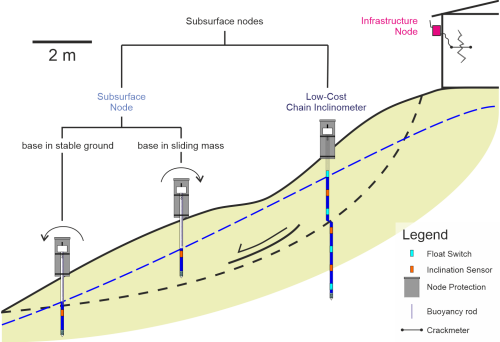
The general measurement concept, with the use cases and measurement principles of these three sensors, has been described in the overview section. For reference, the measurement concept figure is shown again below.
Concept
The use case of the SMP are shallow rotational landslides. In those, the rotational movement inside the landslide body is measured by the inclination sensor in the subsurface and the SMP acts as a stiff rod which tilts as a whole (orange in previous figure). Additionally, a water sensor is included which measures the water level (blue in previous figure). The SMP is located inside of a borehole of 1 inch diameter with a steel or PVC casing, the installation of which is explained in detail in the installation section.
The SMN consists of a water level sensor at the bottom of the borehole, above which a filter part is attached which corresponds to holes that are drilled in the borehole casing. Above the water sensor part, a 3D-printed joint connects it to the inclination sensor above (see figure below). The inclination sensor is located in between two joints which are exactly one meter apart from each other. All parts are connected using M8 threaded rods (in the middle of figure below) and M8 fastening lugs (10 in material list). This is explained further in the installation section. The general structure is displayed in figure \ref{fig:senscon}.
Materials
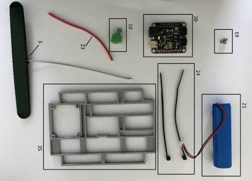
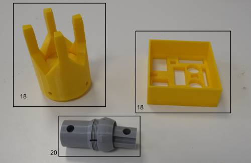
The Materials needed for the construction and installation of the SMN are displayed below and listed in tables 1 and 2. The numbers in the tables correspond to those of the image. Detailed material lists with links and approximate costs can be found on the website.
Basic tools such as pliars, cutters, screwdrivers, allen keys and a gas torch are needed. Also, a multimeter is of great help. It is recommended to do the first construction steps in a workshop. Basic knowledge about electronics is required for the construction.
Table 1: Material list for the inclination sensor.
| Nr. | Amount | Description |
|---|---|---|
| 5 | 1 | Step Counter |
| 6 | 12 | Solder Connector |
| 7 | 35 cm | 6-core cable |
| 8 | 75 cm | 6-core cable |
| 9 | 2 | Threaded rod 35 cm |
| 10 | 4 | Fastening lugs M8 |
| 11 | 44 | Grub screw M8, 2cm with Hexagon socket |
| 19 | 1 | Inclination Sensor |
| 20 | 1 | Joint 38 |
Table 2: Material list for the water sensor.
| Nr. | Amount | Description |
|---|---|---|
| 12 | 1 | Threaded rod M8 25cm |
| 13 | 3 | M8 Nut |
| 14 | 1 | G1/4 Pressure Transducer Sensor 10 PSI |
| 15 | 20*40 cm | Filter fleece |
| 16 | 1 | M8 Threaded connector 40mm |
| 17 | 1 | Cable tie |
| 21 | 2 | Filter 38 |
| 22 | 1 | WLS 34 |
3D Printing
The design relies on 3D-printing of sensor housings, joints and miscellaneous other parts. If many sensors are to be constructed, a good 3D printer is recommended. For lower quantities or test installations, lower grade 3D printers are no problem. The files on the website have been printed before with printers by Ender, Snapmaker and Ultimaker.
All the 3D printing files can be accessed on the website under the following link: \todo{links for printing files}. PETG or ASA filament is recommended for best stability and durability. For best results, it is recommended to use good quality filament and a high print density to avoid breakage. Also, sensitive parts, such as joints and the head cap need to be transported very carefully to avoid breakage, especially in case of the bottom joint when it is already connected in the laboratory.
Construction and Installation
Preparation of Sensors
Before installation of the sensors in the field, the water and inclination sensors have to be prepared into their housings, connected to the 6-core cable and the connections have to be made watertight. This process, which should ideally be performed in a workshop, is explained in this section.
Water Sensor
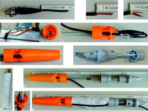
The assembly/preparation of the water sensor is displayed in the figure above. The following steps are necessary:
- Take the water pressure sensor and cut the cable at about 8 cm (a in figure above)
- Remove the black isolation in a way so that about 2.5 cm of the wires are exposed, then remove the isolation of the individual wires for about 0.5 cm (b, c in figure above)
- Perform the same steps for a 1~m piece of wire, removing the insulation of the red, black and orange wires
- Put the sensor in a vice wrench and connect the sensor to the cable using solder connectors (black to black, red to red, green to orange) as in d in figure above
- Install nut and threaded rod in insert for the pressure sensor, next put nut on the threaded rod which is installed to pressure sensor and tighten it using a wrench, additionally put a connector on the threaded rod (e, f in figure above)
- Route cable through insert for pressure sensor befor putting the sensor in, otherwise the cable won't fit (f in figure above)
- Install cup for pressure sensor (g in figure above)
- Put nut on the threaded rod which is installed to pressure sensor and tighten it, additionally put a threaded rod connector on the threaded rod (k in figure above)
- Assemble the joint and filtercap for fleece by putting the connectors in the joint and screwing in the threaded rods (h in figure above)
- Connect filtercap and joint to the water sensor with a threaded rod (i in figure above)
- Add the fleece in a roll around the threaded rod between water sensor and filter cap, then route the cable through filtercap and joint (l in figure above)
- Optional: install zip tie to ensure that the fleece is held in its place
- Prepare 45 ml Epoxy-mixture (2 parts epoxy, 1 part hardener), and add into the water sensor
Inclination Sensor
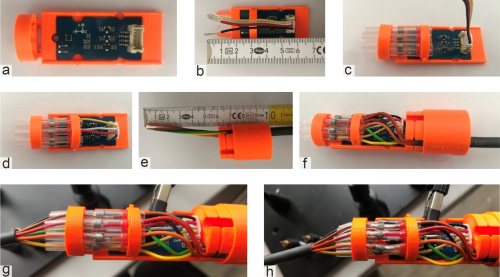
The assembly/preparation of the inclination sensor is displayed in the figure above. The following steps are necessary:
- Put the Step Counter sensor (5) in the proper slot of the 3D print (22) as shown in a in figure above; Optionally, the Step Counter can be glued onto the 3D print for better fixation
- Glue the cable holder, which belongs to the primary 3D printed part, onto it with instant glue
- Install the cable for the Step Counter and cut it to a length of 5.5 cm, removing about 1 cm of isolation of the wires (b)
- Put short cable into WLS 24 (22.2) and remove approximately 5 cm of outer isolation and 1 cm of inner isolation.
Connecting the Parts
Installation in the field
With the prepared sensors, installation in the field should be relatively easy for the short SMN, if a drilling has been prepared. Depending on whether a steel casing is inserted directly or a PVC casing is pre-drilled, the drilling process varies. Yet, the insertion of the sensors and installation of protection and Measurement Node is the same, nonwithstanding the drilling process (see figure below).
Drilling
This process has been tested with various methods. We found the easiest method for shallow depths to be to directly hammer in a steel pipe with a jackhammer or a small ram core drill (see figure below). After this process, the pipe top usually is deformed and needs to be cut. For this process, a manual or battery powered saw is recommended. This method can be difficult in very blocky geology, where pre-drilling is preferred.
Installation of Sensors
This section deals with stage 2 in the figure before the previous. When the drilling casing is installed, the prepared sensor (figure before that one) can be installed by the following steps:
- Measure the depth of the borehole
- If depth is below 1.5~m, remove the upper joint (the upper head will take the place of the upper joint)
- Put the prepared sensor in the borehole up to the upper joint or until it reaches the bottom of the borehole.
- Once the upper joint reaches the top of the casing, there are several ways to go:
- if you have less than 35~cm missing, add a threaded rod and cut it so it will end up about 2~cm above the casing once the sensor is inserted fully into the casing.
- if you have between 35~cm and 1 meter to go, you can install one long threaded rod like in option a), or install two threaded rods with a joint in between or simply a nut to connect two threaded rods.
- if you have about 1 meter or more left, you can install a second inclination sensor and should read in the LCI document about it.
- if applicable, you can also cut the PVC or metal pipe to the appropriate length, depending on how much of it is visible on the surface.
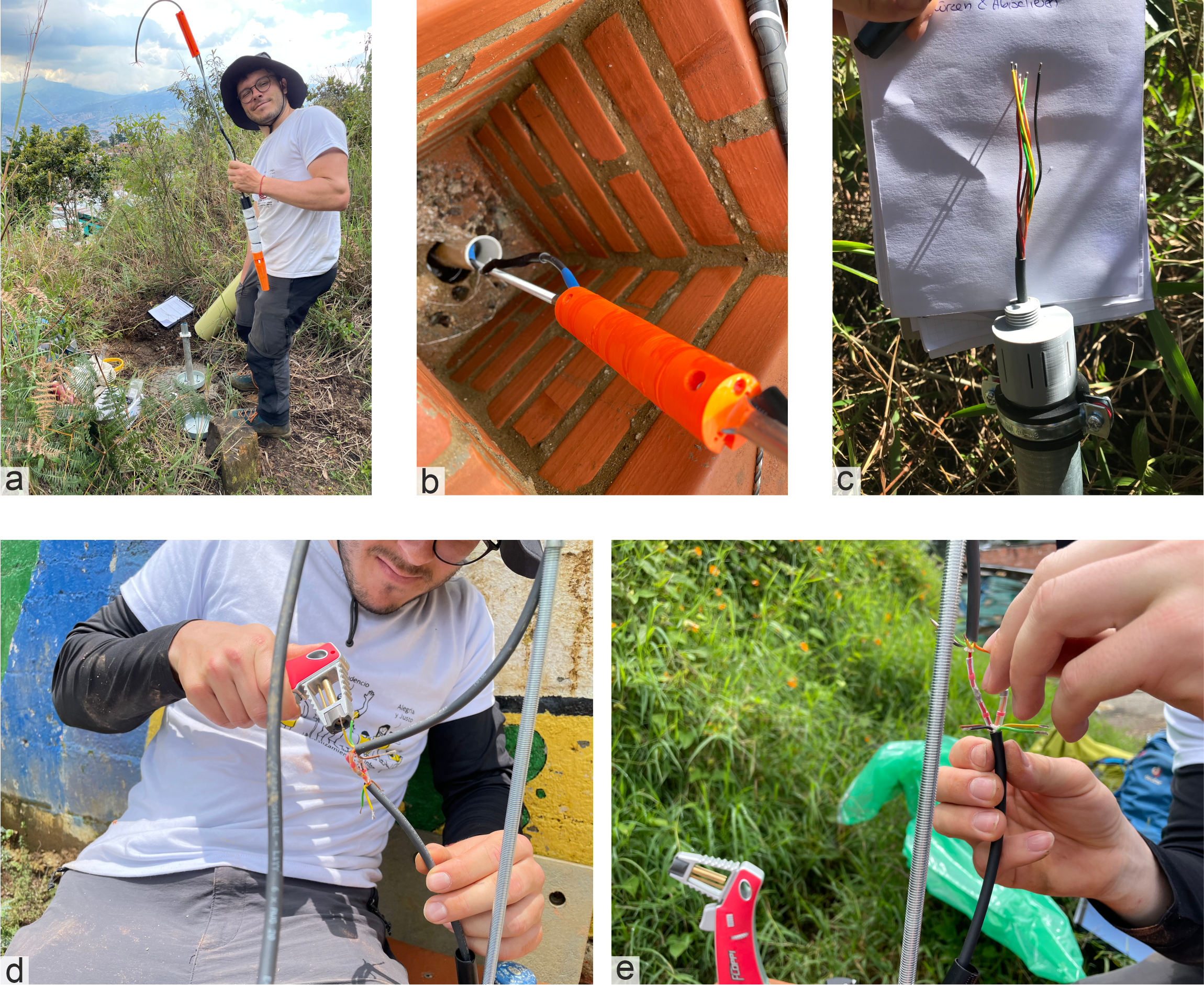
- The length of the 6-axis cable should extend about 50~cm above the casing in the end, to make removal of the Inform@Risk Measurement Node possible. Remember to cut the cable through the joints before putting the joints in the casing or adding the cable to the Measurement Node.
- If you need to increase the length of the cable, you can do so as follows:
- Add a 15~cm piece of heat shrink tubing over one side of the cable and slide it down or up at least 30~cm
- Remove about 3~cm of the outer shielding and about 1~cm of shielding from each wire from both sides of the cable (see e in figure below)
- Add solder connectors (nr. 6 in table 1} and materials figure) over each of the individual wires
- Use a gas burner to connect the wires by liquifying the solder and shrinking the heat tubing of the solder connectors (d in figure below)
- Once all wires are connected, move the 15 cm piece of heat shrink over the top and shrink it over both sides of the wire
- Fix the wire with cable ties to the threaded rods (b in figure below)
- At the top of the casing, once the rod with the sensors and joints is installed fully, you should have about 50~cm of wire left. To connect the cable, follow the following steps:
- First, move the cable through the Head Cap (nr. 18).
- Then get your Measurement Node with the prepared cable gland and move the cable through the latter. Pull the cable into it about 10-20~cm.
- Remove about 15~cm of insulation from the cable and some milimeters from the individual wires (c in figure below)
We recommend to assemble as much as possible in the workshop/laboratory before going in the field to make the installation on site more efficient. In addition to the previous recommendation, for the nodes that are protected with PVC piping, although it is recommended to leave 50 cm of 6-axis cable, in some cases it is pertinent to leave a little more given that for future maintenance and revision of the node it is more practical that it can come out of the protection piping completely and this will allow a longer length of cable than the length of the protection piping.
Installation of Sensor Protection
For the sensor protection (step 3 in figure 1), two variants are proposed, which vary in the way their visible parts on the surface are laid out. One solution, from here on called PVC Pipe and Foundation, is the 'functional' approach, where looks are not as important. This is proposed for remote, non-urban regions. The second solution, Totem has been designed by the urban planning team at Leibniz-Universität Hannover (LUH) and is therefore focused on the incorporation of the sensor in the urban context.
PVC Pipe and Foundation
The more technical and very simple solution with pvc pipe and foundation only needs a limited amount of parts. The tools needed are a drilling machine, a saw, a file and some keys.
The necessary materials are listed below:
- PVC pipe including two lids and drillings for threaded rods and inclinometer casing
- Foundation with three threaded rods sticking out vertically
- Rubber band with 120 mm diameter and about 5 mm strength
- Nuts and washers for threaded rods
- Various 3D printed parts: Enclosure for solar panel on side or on top, spacers for pvc pipe
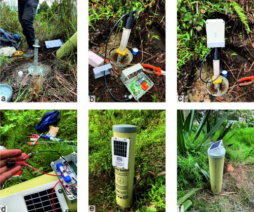
The pipe is fixated with a small, 20×20~cm concrete foundation, which holds three threaded rods of approximately M8 size (about 8~mm diameter). Then, the lid of the PVC pipe si put on backwards (a in previous figure) and fixed to the foundation with nuts and washers. Then, once the Measurement Node is attached to the SMN (b, c), The solar panel can be attached to the PVC pipe. For this, there are two options: Have the solar panel on the side (e) or on top (f) of the PVC pipe. The lid of the PVC pipe can be attached to the pipe itself using special screws, so it can stille be removed for maintenance works, but not easily be tampered with by third parties.
Totem
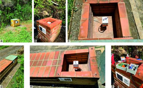
The Totem provides a visually more appealing solution to the sensor protection and a better integration into public space. Details for the design can be accessed from LUH here \todo{add LUH links}. As visible in the next figure, the construction that was used in the Inform@Risk project consists of a simple brick design and lids made of plastic wood.
Bench
Like the totem, the bench design provides a better integration of the technical part into public space. The technical part surrounding the drilling and Measurement Node is identical, though.

