This is an old revision of the document!
Table of Contents
Software Installation for Measurement Nodes
Introduction and Overview
This document provides the necessary steps required for the installation and configuration of the Inform@Risk LoRa Nodes. The Inform@Risk LoRaBasis software requires only open-source libraries and dependencies to be installed in order to setup the LoRa nodes. For more information about the hardware on the PCB, please check the corresponding hardware documentation under www.informrisk.alpgeorisk.com. A short overview of the hardware is given in the subsequent section.
Hardware Overview
The circuit board needed for this software is called 'Inform@Risk PCB'. It consists of about 100 components, including a high quality analog-digital converter (ADS 1220), an accelerometer (ICM20948) and Thermometer as well as a Barometer (BMP388). The microprocessor used is an Arduino MKRWAN 1310, with an SAMD21 processor and Murata CMWX1ZZABZ LoRa chip.
Additionally, a high-quality inclination sensor (Murata SCL3300) can be added to the board and connected using a 6-pin connector. If a subsurface sensor is attached to the board, an additional accelerometer (BMA456) is connected.
Software Overview
- Various Arduino Libraries to be downloaded in the Arduino IDE:
- SPI.h (installation not needed)
- Libraries to be downloaded from the Inform@Risk GitHub page:
- agr_ads1220.h
- Seeed Studio Step Counter/Bosch BMA456: edited by AlpGeorisk (arduino\textunderscore bma456.h)
Hardware Setup to Upload and Test the Nodes
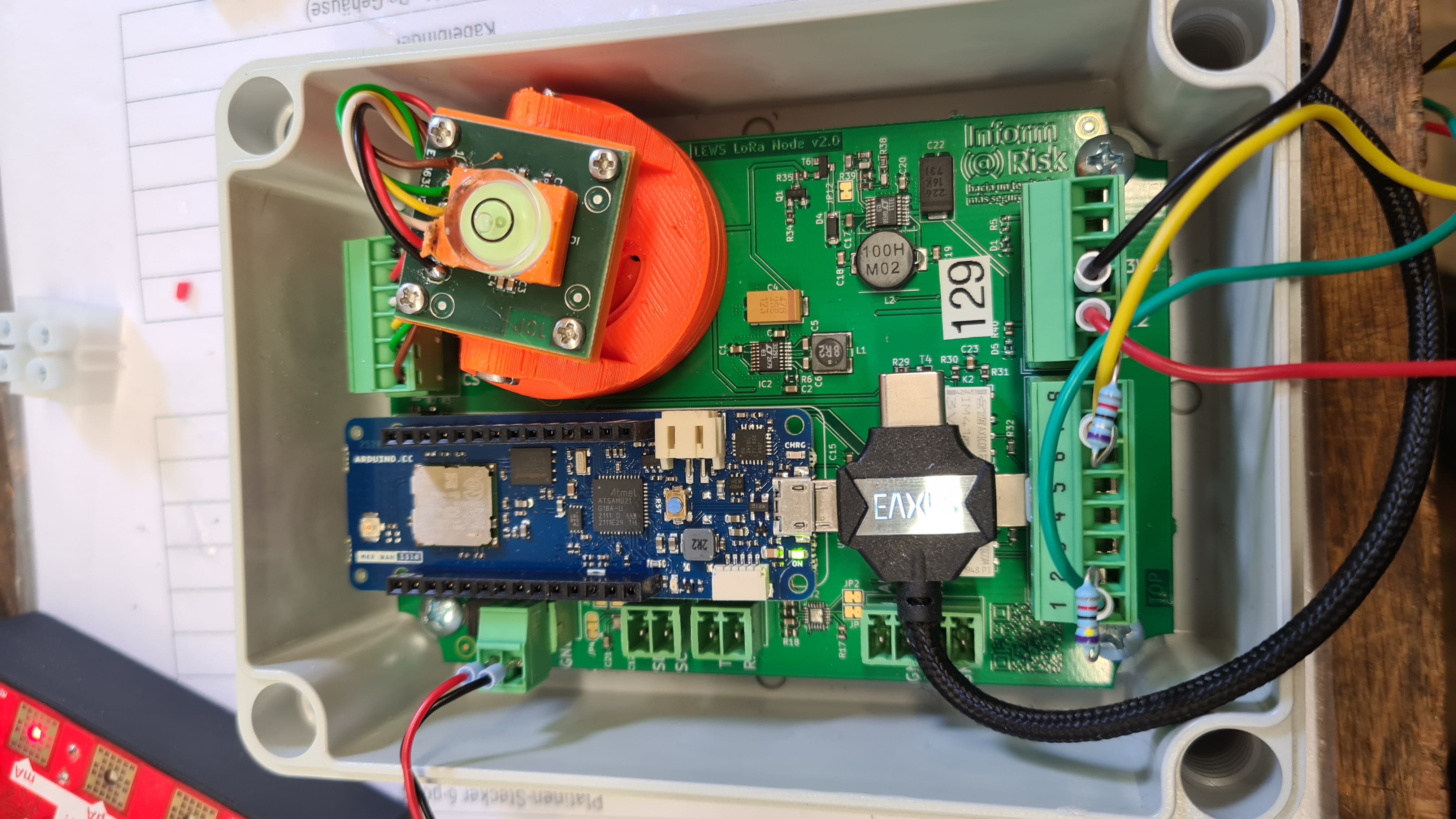
In order for the nodes to work, the PCB has to be prepared as shown in the last instruction manual (1 - Measurement Node). A power supply, such as a battery or solar powered lid, or a power supply with 3.5-15~V is needed since the nodes can not be powered by USB any more after removing the connection (Step 6 in part 3.1 'Preparation of the PCB and bottom part'). Then, a micro-usb cable is used to connect the Arduino to a computer. Please note that this micro-usb cable needs to be able to transmit data (charging-only cables don't work!). Also, because of the tight space in the enclosure, an angled plug is convenient or even necessary. An example setup is shown in the subsequent figure.
Setting up Inform@Risk Software
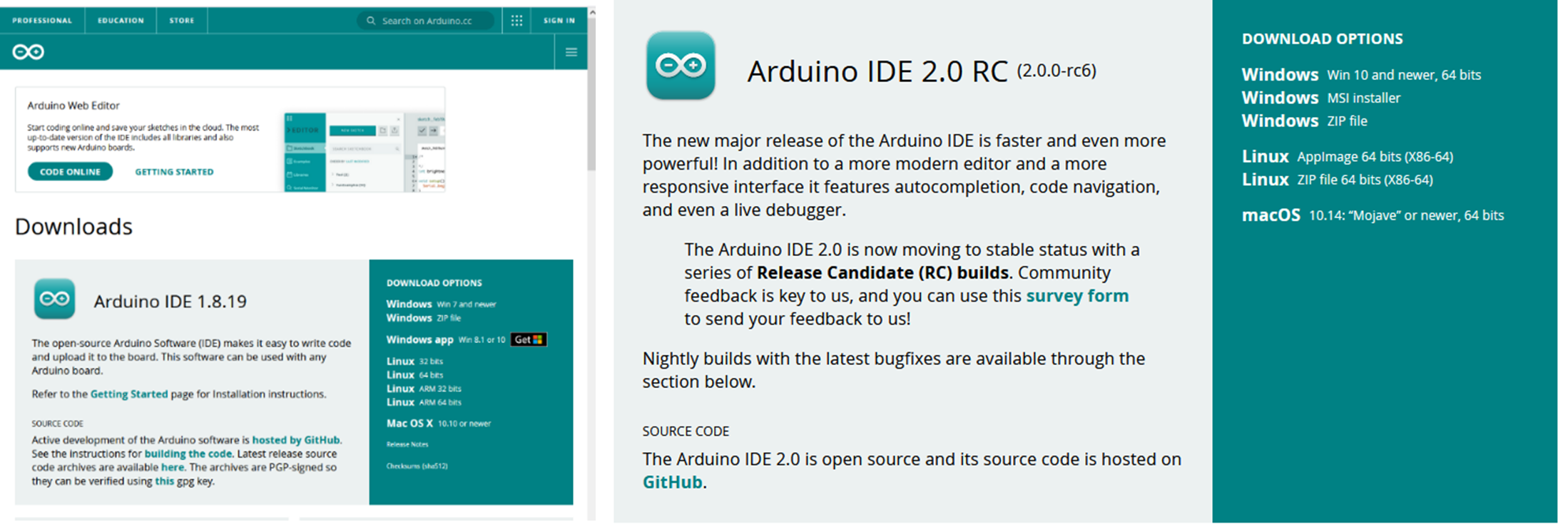
First, install the Arduino IDE from https://www.arduino.cc/en/software. Either the regular Arduino IDE or the newer Arduino IDE 2.0, which has updated editor functionality, can be used. The following screenshots are from the regular IDE, v. 1.8.19 (see following figure).
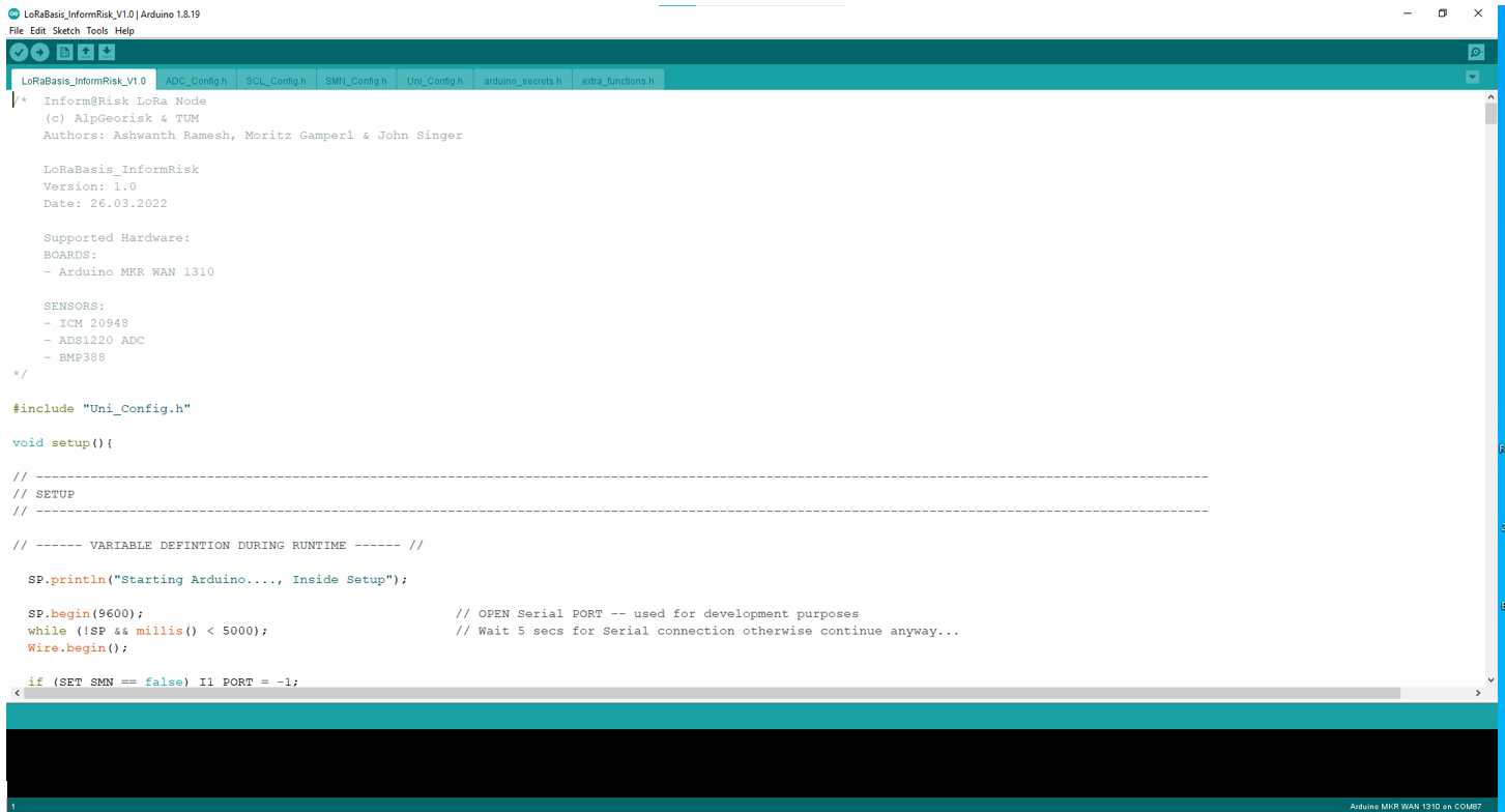
When the IDE is installed, open the file “LoRaBasis\textunderscore InformRisk\textunderscore VXX”, with XX representing the current version number. You will see a similar screen to the one below.
The tabs correspond to the ‘.h’ files in the folder in which the Arduino file is located. The .h files have different functions, which are explained below. If the Inform@Risk board is used, usually only the Uni\textunderscore Config.h file needs to be changed by the user.
The tabs' functions are as follows:
| Name | Functionality |
|---|---|
| LoRaBasis_InformRisk | Main Code, which houses the main setup and loop functionality |
| ADC_Config.h | Configuration file for the ADC (Analog‐Digital Converter) ADS1220 |
| SCL_Config.h | Configuration file for the SCL3300 inclination board |
| SMN_Config.h | Configuration file for the Subsurface Sensors on the Subsurface Measurement Node |
| Uni_Config.h | Universal configuration file: Stores universal parameters such as measurement and sleep time and sensor states |
| arduino_secrets.h | Secret App EUI and Key which are stored on the gateway server for connection |
| extra_functions.h | Some additional functions |
When the libraries are installed correctly, the code should compile without problems. There are several issues that could occur, we will add possible problems in a future version of this guide. If you have problems, you can contact us under moritz.gamperl@tum.de.
Settings in Uni_Config Tab
In this tab, the general settings are performed. The Uni_Config file is structured as follows:
- Include libraries and necessary files
- Universal Configurations: Variable and Timing definitions, sensor states
- Hardware Configuration
- Include extra configuration files for SCL, SMN and ADC, as well as functions
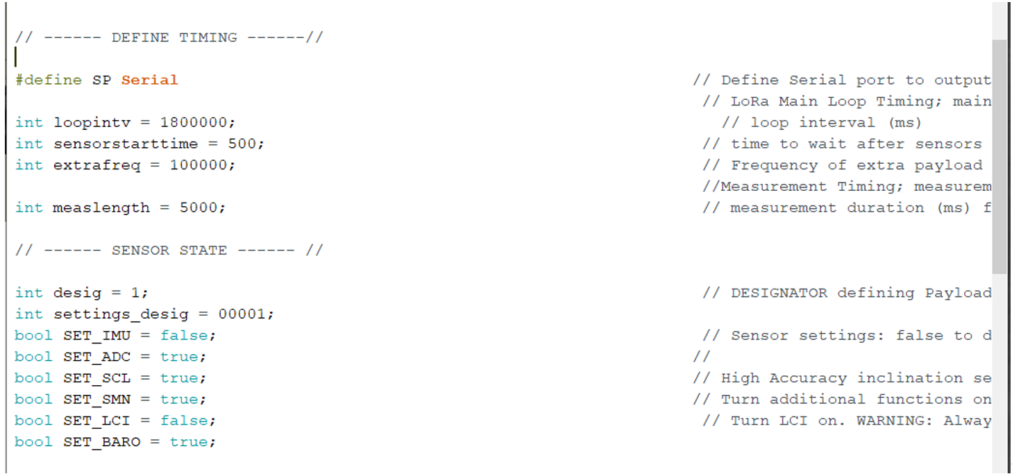
Of these parts, only the timing definitions and the sensor states need to and should be changed by the user (see picture below).
Each of these parameters is described shortly on the right side as comments.
Serial Output
The first command # define SP Serial defines which serial port is used. This is important for debugging: Because the Serial monitor of the Arduino via USB shuts down once the processor goes into deepsleep-mode (described in detail in the section on deepsleep), it is possible to change the serial output to the serial ports on the PCB (RX, TX). This way, subsequent cycles after the first deepsleep command can also be read out from the serial port. If the serial ports on the PCB are used, the command needs to be changed to SP Serial1.
Loopintv
Loopintv controls the interval of one cycle, including initialization, measurement, data transmission, powerdown, sleeping and powerup. This means that the sleeptime itself is calculated each cycle by subtracting measlength , sensorstarttime and the rest of the calculation time from the total loopintv. extrafreq is not used for now (v 1.0).
The sleeptime is calculated as follows:
sleeptime = loopintv - (measlength + sensorstarttime)
Sensor State
The Sensor State section is used to turn on/off the different sensors which are connected on the board or can be attached to it. To turn a sensor on, simply write “= true” after the corresponding variable. This is the main section which needs to be changed when setting up a sensor either in the field or when preparing it beforehand. Please note that for the current PCB version (V 0.2), no IMU is attached on the board, so this is always false. Desig and settings\textunderscore desig change dynamically in the loop and don’t have to be adapted.
These settings can be seen as general toggles for the different sensors. If they are not turned on, all subsequent settings (for the ADC e.g. in the “ADC\textunderscore Config.h” file) are disregarded. If, for example, the SMN is attached, but with settings different from the default (explained in the SMN section), the SMN must be turned on here and the specific settings have to be changed in the SMN\textunderscore Config.h file.


