Table of Contents
Basic Concepts of the Measurement System
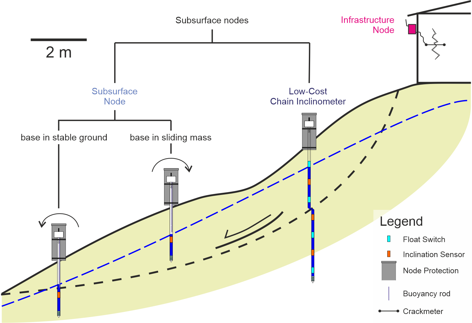
All sensors in the system are based on one basic measurement node design, to which additional sensors can be attached easily. This way, the system can be very versatile while keeping the cost low. The basic measurement node can simply be attached to walls to measure inclination or e.g. crack elongation with an external crackmeter (figure below). In this case, we call it 'Infrastructure Node'. When subsurface sensors are attached to it, we call it 'Subsurface Node' or 'Low-Cost Inclinometer', depending on the drilling depth and according number of sensors attached.
The Low-Cost Extensometer on the other hand can be used to measure elongation along an axis, be it vertically (e.g. in a borehole) or horizontally (e.g. across a slope). It consists of the measurement wire, the measurement tools in a shaft and a potentiometric sensor. The latter is then attached to the ADC (Analog-Digital Converter) of the measurement node.
All measurement nodes should be connected to at least two LoRa gateways, which should ideally be located in safe spots, with as good as possible line of sight to all sensors. There is also an instructional manual for the LoRa gateway, but it is more general in comparison to the other manuals. This is because the gateway will be very specific to the site and not as versatile as the individual sensors. Still, the manual contains the general overview of what is needed. If you have questions about this, don't hesitate to contact us.
The integration of the sensors into public space is very important, especially in urbanized regions, because it can improve the acceptance of the system by the local population. As part of the social component, it is further addressed in section \ref{c:soc}.
Structure of provided Materials
In order to make reproduction of the system as easy as possible, several files and documents are published on the project website and this wiki: project website. The can be divided into instruction manuals, datasheets and 3D printing files. All software is published on the project's GitHub page.
In the following sections, all documents are listed and explained whenever necessary.
Instruction Manuals
We created several instruction pages. Starting, an overview of the system and the basic measurement node, which is needed for all other measurements, is given. Then the attachments (Subsurface Probe and Low-Cost Inclinometer) are addressed. The Low-Cost Extensometer is last since it is based on a slightly different approach. The last section is the LoRa-Gateway, which is only explained briefly since it is very individual for the respective requirements. The pages are listed in the following (clicking on the headlines directly leads you to the respective wiki page):
- Overview
Overview and general concepts. - Measurement Nodes Assembly
Assembly of basic measurement nodes: PCB and 3D prints. - Software Installation
Necessary steps for installing the software of the measurement nodes are explained. - Subsurface Probes
Assembly and installation of subsurface probes, which extend about 1-2 m into the subsurface. - Low-Cost Inclinometer
Assembly and installation of Low-Cost Inclinometer, which extend about 3-6 m into the subsurface. - Low-Cost Extensometer
Assembly and installation of the horizontal and vertical Low-Cost Extensometer. - LoRa Gateway
General recommendations and requirements for the LoRa Gateway.
Datasheets
For some parts of the system, datasheets were produced. Like the other downloadable material, they can be downloaded from the resources page. Third-Party datasheets for the sensors and some of the components that were used are referenced in the respective instructional documents.
3D Printing Files
3D printing files are supplied for the measurement node, the Subsurface Probes (they are identical to the ones needed for the Low-Cost Inclinometer) and the Low-Cost Extensometer. They are sorted in this way on the website. Here, a short overview is given. Detailed instructions can be found in the individual instruction pages.
The 3D printing files for the measurement node comprise:
- The files for the lid, which houses the power supply. Therefore, there are different versions, depending on if it is solar- or battery powered.
- The files for the inclination sensor mount, which is attached to the PCB directly and necessary to be able to tilt the inclination sensor, so it is horizontal independent of the measurement node orientation.
Social aspects: integration into public space and community warning
For a better acceptance and identification of the instruments by the community, the designs of the sensors should be accompanied by elements that incorporate it into the public space. These designs in an urban context should clearly mark the sensors and their purpose instead of trying to hide them.
In our installation in Medellín, Colombia, interventions were carried out to improve public spaces made up of benches and small seats, which incorporated sensors inside them. The acceptance of these in general terms was positive. It is essential that when replicating this, joint planning is carried out with the community in terms of infrastructure for the improvement of public space.
These public interventions are described further in the section Basic Concepts of the Measurement System.

